High-performance light collection optical system design [patented]

With LED light sources using an imaging system, LED image formation occurs on the incidence end surface of a light guide and illumination distribution is uneven due to an aberration as seen in image (b) above. On the other hand, U-Technology’s non-imaging optical system can reproduce the circle shape of the light guide and results in even illumination distribution as seen in (a) above.
High illuminance
Light emitted from LEDs based on our proprietary optical system is condensed onto the light guide end surface to achieve higher and more even illuminance, which makes it possible to replace metal halide lights.

* Based on U-Technology’s research
*φ12 straight type (WD=100)
*The values are observed illuminance values, not guaranteed values.
Feedback function (BTO)
Our proprietary technology maintains a constant light output regardless of room temperature and time.
•Less need for illuminance management and device initialization
•Stable operation of manufacturing line
Three different standard external control modes
•Serial communication: RS-232C (240-step)
•Digital: 8-bit digital control (240-step)
•Analog: 0-5V (960-step)
(Selectable using the mode selection switch)
ON/OFF switching
Lighting can be switched ON/OFF.
•Lighting is turned ON for inspection and OFF for downtime to save energy.
•To keep lighting ON during device adjustment work, lighting mode can be reversed easily using the mode selector switch.
Projection lens
Type description
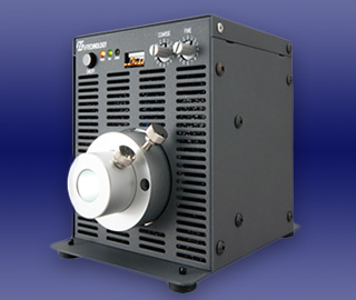
High-Power R/G/B/UV LED Light Source
| Type |
UFLS-501-※※※-※※ |
| LED luminescent color |
Red / Green / Blue / UV |
| Output flux |
700 lm / 1400 lm /500 lm / 5 W |
| Correlated color temperature |
620 nm / 520 nm / 460 nm / 405 nm |
| LED life |
*30000h (10000h for UV) |
| Light emission system |
Constant-current light emission |
| Light control system |
Variable current control |
| Light control |
Manual: Digital setting by means of light control knobs 00: OFF, 10-ff (240-step) |
External serial: Setting by means of RS232C communication 00: OFF, 10-ff (240-step)
External digital: Setting by means of 8-bit parallel signal 00: OFF, 10-ff (240-step)
External analog: 0-5V (effective range: 0.32-5V) Approx. 960 steps by means of internal 10-bit control 0.15V or below: OFF |
| ON/OFF control |
Photocoupler insulation, built-in CRD |
| Error detection |
When fan stoppage, LED overheat or LED breakage is detected, the alarm indicator lights up and the LED turns OFF. |
| Input protection |
By fuse |
| Joint diameter |
φ8-12 |
| Input voltage |
Rating: 24V DC Range: 21.6-26.4V DC |
| Power consumption |
72W |
| Interface |
D-SUB25PIN (female) |
| Use environment |
Temperature: 0-40℃ Humidity: 20-85%RH (non condensing) |
| Storage environment |
Temperature: -20-60℃ Humidity: 20-85%RH (non condensing) |
| Cooling method |
Forced cooling (air inlet: front, air outlet: rear) |
| Outside dimensions |
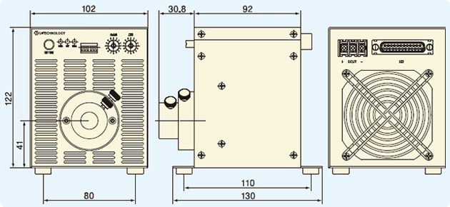
102 x 122 x 92 mm (protrusions not included) |
| Material |
SECC and acrylic coating |
| Weight |
Approx. 1.2 kg |
| External standards |
RoHS-compliant |
*Variable depending on operating environment temperature. This is not a guaranteed value.
Note: Light guides must be heat resistant, if used in conjunction with this device.
Spectral characteristics of LED
External control connector pin assignment
| Name |
Connector Model |
Pin # |
Signal name |
I/O |
Hi |
Lo |
| External control connector |
D-sub 25-pin |
1 |
Commorn (+) |
I |
|
|
| 2 |
TxD |
O |
|
|
| 3 |
RxD |
I |
|
|
| 4 |
|
|
|
|
| 5 |
|
|
|
|
| 6 |
|
|
|
|
| 7 |
GND |
I/O |
|
|
| 8 |
|
|
|
|
| 9 |
Bit 0 (LSB) |
I |
Inact |
Act |
| 10 |
Bit 1 |
I |
Inact |
Act |
| 11 |
Bit 2 |
I |
Inact |
Act |
| 12 |
Bit 3 |
I |
Inact |
Act |
| 13 |
Bit 4 |
I |
Inact |
Act |
| 14 |
Bit 5 |
I |
Inact |
Act |
| 15 |
Bit 6 |
I |
Inact |
Act |
| 16 |
Bit 7 (MSB) |
I |
Inact |
Act |
| 17 |
On/Off + |
I |
*2 |
*2 |
| 18 |
On/Off – |
I |
*2 |
*2 |
| 19 |
Analog + |
I |
|
|
| 20 |
|
|
|
|
| 21 |
Analog – |
I |
|
|
| 22 |
|
|
|
|
| 23 |
Alarm |
O |
Abnormal |
Normal |
| 24 |
LED On |
O |
ON |
OFF |
| 25 |
Rele Alarm |
I |
Inact |
Act |
*1. Act: Active Inact: Inactive
*2. Negative logic: On/Off +: H AND On/Off -: ON only when L, Positive logic: On/Off +: L OR On/Off -: ON when H
*3. To cancel an alarm, set to Lon above Ims. For light control via serial communication, set the light control volume again.
Example:
Standard base

*For other base profiles, contact our sales representative.
BTO item


